AZ ScQRPions/W5JH Paddle Instructions
Copyright Ó 1/2004 by Jerry Haigwood
Unpacking the Parts
The paddle is shipped in a single small padded envelope. Remove the parts from the envelope and compare them with the parts list. The base, arms, posts, and stop are all wrapped in tissue. The hardware is sealed in a small coin envelope and the finger pieces (AKA guitar picks) and Teflon tape are sealed in an additional coin envelope. Open up the coin envelope marked "HDW" and dump the parts into a small plastic bowl (a cleaned plastic butter dish works well). You can also remove the Teflon tape and finger pieces but keep them separated from the hardware to prevent scratching.
Finishing the Brass
Before assembling the paddle, you will probably want to finish the 6 large brass parts. Sanding with 4 grades of sandpaper will finish the brass parts nicely. You may also want to polish the parts and finally you may want to add a coat of clear lacquer. You can refer to pictures of this operation at
http://www.swlink.net/~w5jh/finishing.htm.You will need 4 grades of sandpaper – 100 grit, 150 grit, 220 grit, and 400 grit. These can be found at building supply houses and hardware stores. A single 8.5inch by 11inch sheet of each grit rating will be plenty. Find a flat surface to do the sanding on. A table saw, router table or maybe even a kitchen table (if you can talk your spouse into it) will all work. Use tape around the edges to hold down the sandpaper to the surface. Start with the 100 grit paper. Place the paddle base on the paper with the edges of the base parallel to the paper. Sand the part in a straight line using short back and forth strokes. Continue sanding the part on all 6 sides until the part is clean, smooth and there are no dings or saw marks showing. In a like manner, sand the remaining brass parts. You now need to attach the small wire to the paddle arms. Refer to the section "Attaching the Ground Wire" below. Once the 100 grit sanding is completed and a small wire is attached to each paddle arm, you are ready to move to the 150 grit sandpaper. Attach the paper to the flat surface using tape and sand all parts. Note that the paddle arms can only be sanded on 5 sides since the bottom of each arm has a small wire attached and the bottom of the base does require any additional sanding. Again the parts should be sanded in a straight line. The sand marks in the parts will be smaller with the 150 grit paper and the finish will be smoother than after the initial sanding with the 100 grit paper. In a like manner, sand the parts using the 220 grit paper and finally the 400 grit paper. Upon completing the sanding, the parts will have a nice smooth and satin finish. Many people may want to stop here. However, some type of protection of the finish will be needed or the brass will begin to tarnish again. Clear lacquer can be spayed on the brass to give it a longer finish life. If you choose to lacquer the parts, be sure to mask off the screw holes for the electrical contacts on the arms and posts. You can use old 4-40 screws inserted in the holes to do the masking. At least one of the tapped holes on the bottom of the base will need to be masked off for electrical contact.
If you choose to polish the parts, you need to do it prior to lacquering. I can recommend two polishes I have used successfully. Flitz is a polish used to shine and protect metals. It is available from many gun stores. Another product, MAAS, is also an excellent polish and is available from Home Depot. Both polishes should be used sparingly. If you want a mirror like shine, use your Dremel or similar tool with a polishing bonnet to do the polishing. At 25,000 RPM, it doesn’t take long to get a mirror like shine.
Attaching the Ground Wire
Ground wires need to be attached to each arm to insure good conductivity to ground. You will need a 40-80 watt soldering iron with a clean chisel tip. The wire must be attached directly below the spring recess hole on the bottom of the arm. Prepare the wire by bending one end of each wire approximately 1/16 inch. Attaching these wires will create a left and right paddle arm. The two arms are identical until you decide which one will become a left and which one will become right. When soldering the wire onto the arms, make sure the spring holes will face one another when you are finished. Start the process by getting your soldering iron heated up. Brass is an excellent conductor of heat. It will take a lot of heat to solder the small silver plated wire. Once the iron is up to temperature, apply a small amount of solder to the tip to wet it. Apply the iron to the paddle arm to be soldered and let it heat. Keep testing the arm to see if it will accept solder. After the arm starts accepting solder, attach the bent end of the wire to the brass arm. Remove the iron and allow the solder and arm to cool. Note: the brass ARM will stay HOT for a long time. Unless you want to get rid of your fingerprints, resist the temptation to pick it up! After cooling, the arm and wire can be inspected. The solder around the wire has to be kept to a minimum to allow adequate clearance of the arm with the base. You can use a small amount of solder wick to remove any excess solder. You now have a right and left paddle arm.
Assembling the Paddle
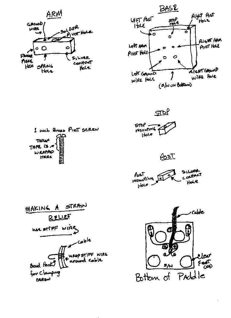
Pick a clean open area with a flat, level surface to do the assembly (kitchen table). Lay a small towel on the surface. It will keep you from scratching the surface and small hardware will not bounce and roll off of the surface after being dropped. Refer to the figure page and
http://www.swlink.net/~w5jh/brasspaddle.htm while assembling the paddle.Use
Turn on your radio, plug in the paddle, HAVE FUN!
Parts List
|
Quantity |
Description |
|
1 |
Brass Base |
|
2 |
Brass Lever Arms |
|
2 |
Contact Post |
|
1 |
Stop |
|
4 |
#4 X 0.093 Nylon shoulder washer |
|
2 |
#4 X 0.250 Nylon shoulder washer |
|
2 |
#4 X 0.125 Nylon shoulder washer |
|
2 |
4-40 X 1 inch brass screw |
|
3 |
4-40 X 1/2 inch brass screw |
|
2 |
4-40 X 1/4 inch brass screw |
|
2 |
4-40 X 1/2 inch silver plated brass screw |
|
2 |
4-40 X 1/4 inch silver plated brass screw |
|
4 |
4-40 brass nut |
|
4 |
#4 Stainless internal tooth washer |
|
3 |
#4 solder lug |
|
4 |
0.200 X 0.44 Clear plastic bumpon |
|
1 |
0.71 lb. X 1/2 inch compression spring |
|
1 |
Left Finger piece |
|
1 |
Right Finger piece |
|
3 inches |
1/2 inch wide Teflon tape |
|
2 |
1inch #30 silver plated bare wire |
Figures