Instructions for the Black Widow Paddle
Copyright May 12, 2008 by Jerry Haigwood, W5JH
Introduction
Thank you for purchasing the
Black Widow paddle. You will find it is
a high quality product that will give you many years of good service. Before assembling the paddle, please read
through the instructions to insure you understand the order of finishing and
assembly. Before you start the finishing operation, you will need to complete
the subassembly process below.
Inventory
Before continuing, it is a good
idea to inventory the parts. The brass
machined parts come wrapped in paper towels to cushion them and to keep them
from cutting the envelope. The two small
coin envelopes contain the smaller hardware.
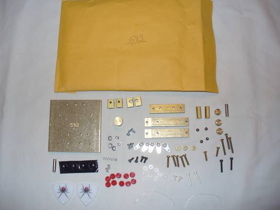
Figure 1 shows a picture of the parts.
 Figure
1
Figure
1
|
Quantity |
Description |
|
|
|
|
1 |
Base
(brass machined part) |
|
1 |
Stop
(brass machined part) |
|
2 |
Arm
(brass machined part) |
|
2 |
Contact
Post (brass machined part) |
|
2 |
Magnet
Post (brass machined part) |
|
1 |
Tensioner
(brass machined part) |
|
2 |
3/16 inch
x 3/4 inch Cylinder Magnet |
|
2 |
4-40 x
5/8 inch Socket Head Silver Plated screws |
|
2 |
4-40 x
5/8 inch Socket Head Black Oxide screws |
|
4 |
4-40 x
1/4 inch Socket Black Oxide screws |
|
2 |
4-40 x
1/4 inch silver plated brass pan head screws |
|
4 |
4-40 x
1/4 inch zinc plated pan head screws |
|
2 |
4-40 x 1/2
inch brass pan head screws |
|
5 |
4-40 x
5/8 inch brass pan head screws |
|
3 |
4-40 x
7/8 inch brass round head screws |
|
3 |
4-40
brass hex nuts |
|
3 |
4-40
brass knurled nuts |
|
5 |
#4
stainless steel inside star lock washer |
|
10 |
Red
knurled heads for #4 socket head screws |
|
2 |
Finger
pieces with black widow |
|
4 |
3/16 inch
chrome steel balls |
|
4 |
0.200 x
0.44 inch plastic feet |
|
9 |
#4 x
0.063 inch nylon shoulder washer |
|
5 |
#4 ground
lugs |
|
2 |
4-40 x 0.590
inch brass hex standoffs |
|
1 |
3/16 inch
x ¾ inch compression spring |
|
2 |
3/16 inch
O.D. x ¼ inch Compression Spring |
|
2 |
2 inch
#30 Silver Plated bus wire |
Table 1
Before opening the parts,
find a lid from a cardboard box.
Something about 15 inch x 15 inch with a lip of 1-2 inches works
well. Open the envelope and place the
parts in the lid to keep them from rolling all over the place. Using Figure 1 and Table 1, inventory the
parts. If you find a few extra parts,
consider it your lucky day! If you are
short a part, contacts us right away and we will make sure we get you the part(s)
fast.
Subassembly
Before proceeding with
finishing or assembly, you will need to do a small amount of subassembly. First, you will need to press the Red knurled
heads onto the 8 socket screws. There
are 2 Black 5/8 inch long socket head screws, 4 Black ¼ inch socket head
screws, and 2 Silver Plated 5/8 inch
socket head screws. Thread the socket
head screw into one of the brass hex spacers. Using a vice or similar device, carefully
press the Red knurled heads onto the socket screws as is shown in Figure 2.
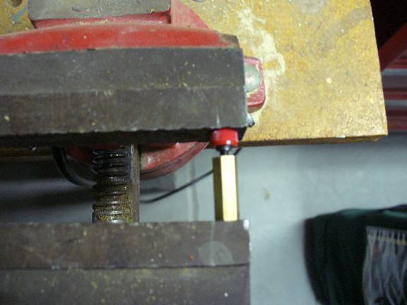
Figure 2
In a similar manner, Red
knurled heads need to be glued and pressed onto the magnets. First, lightly sand one end of each
magnet. Mix and apply a small amount of
2 part epoxy to the sanded end of the magnets (see Figure 2.4). Press the Red Knurled heads onto the
magnets. Allow the epoxy to setup before
handling these parts. See Figure 2.5.
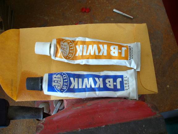
Figure 2.4
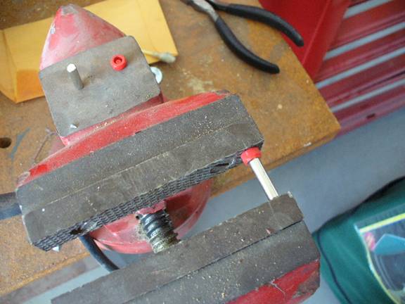
Figure 2.5
When you have pressed all the
Red knurled heads onto all the screws and two magnets, you should have a set of
parts that look like those in Figure 2.6.
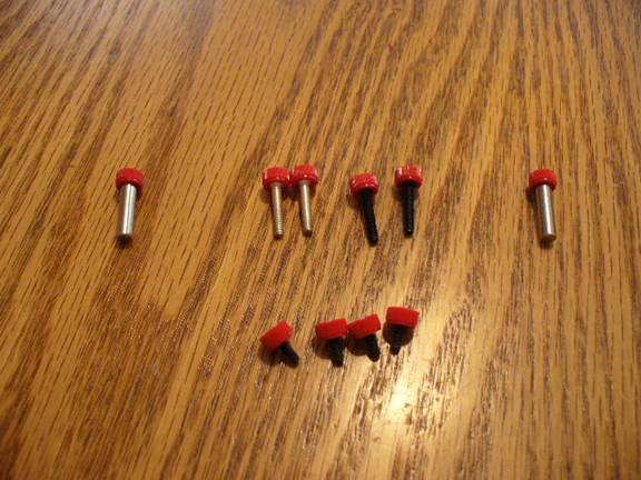
Figure 2.6
Silver Wires
Next you will have the choice
of either soldering the wires onto the paddle arms or waiting until final
assembly and clamping the wires under the magnet attracting screws. If you decide to solder the wires, read on
else you can skip down to “Finishing.”
Next you can solder the 2 inch small (#30 AWG)
silver plated wires onto the paddle arms.
Please note that by soldering the wires onto the arms, you will create a
left and right arm. Before soldering the
wires, sand the arms on the side where the wires will be soldered. The sanding will remove oxidation and make
the soldering go a bit faster. You will
need a good size iron (about 40-50W). Locate
the wires on the bottom side directly beneath the 3/16 inch counter bore hole. After
heating and soldering the wire, DO NOT TOUCH the hot arms unless you want to
remove your finger prints! I’ve been
there and done that and it wasn’t fun! It
will take a good 5-10 minutes for the brass to cool down. Refer to Figure 3 below to see where the
wires are soldered. The arm on the left
is the left arm for the paddle and the arm on the right is the right arm for
the paddle. Please note that the arms
are mirror images of one another. If you
solder the wire on the wrong side, you will end up with two left arms or two
right arms. The repair is not hard just
time consuming sanding solder off the arm!
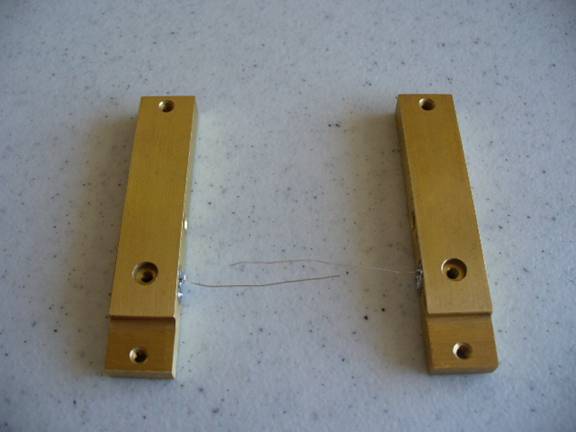
Figure 3
Finishing
The parts are now ready for
sanding and finishing (see the paddle finishing document). Before completing the final assembly, allow
plenty of drying time for whatever coating you use to cover the brass.
Assembly
Welcome back from the
finishing process. I hoped your finish
turned out the way you wanted it. If you
have not yet deburred the holes, you will need to do so now. We are now ready to begin the assembly. In about an hour or so, you will be on the
air sending some of the smoothest code you have ever sent! Let’s get started!
Set the base in front of you
in the lid of the cardboard box. Orientate
it the same as Figure 4 below. The top 3
holes are for the knurled nuts to connect to your cable. The outside holes of the next are for the
contact posts. The center hole is for
the stop. The next 4 holes are used for
the hex posts and for the ball bearing to ride on. The last 4 holes are for the wires from the
arms to go through and for the magnet posts.
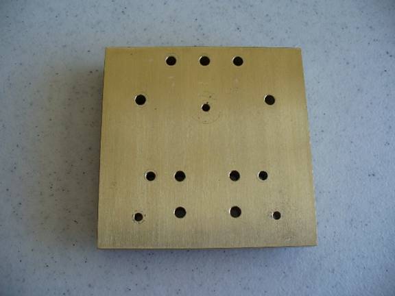
Figure 4
Refer to Figure 5. The stop is assembled to the base using a
4-40 x 5/8 inch brass screw and #4 stainless inside star lock washer. Place the washer over the screw, insert it
into the hole in the base from the bottom of the base as is shown in Figure 5. Using the stop as a nut, screw the stop onto
the screw. Use a small screw driver to
tighten the screw.
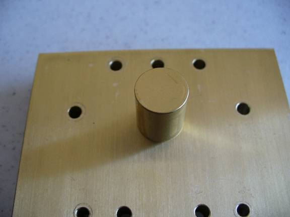
Figure 5
The knurled nuts are mounted
next. Refer to Figures 6, 7, and 8. The two outside knurled nuts are insulated
from the base using small nylon shoulder washers. Gather the following parts:
3 4-40 x 7/8 brass screws
3 4-40 hex nuts
3 4-40 knurled nuts
1 #4 lock washer
5 #4 nylon shoulder washers
2 #4 ground lug
Locate the three holes
used for the knurled nuts. Using a small piece of sand paper, clean off
any finishing material around the bottom of the center knurled nut hole.
Place a ground lug over one
of the 4-40 x 7/8 brass screws. Next
place a shoulder washer over the same 7/8 inch screw. Insert the screw though one of the outside
knurled nut holes in the base from the bottom.
Place another shoulder washer over the screw on top of the base. Screw a hex nut onto the screw and tighten
finger tight.
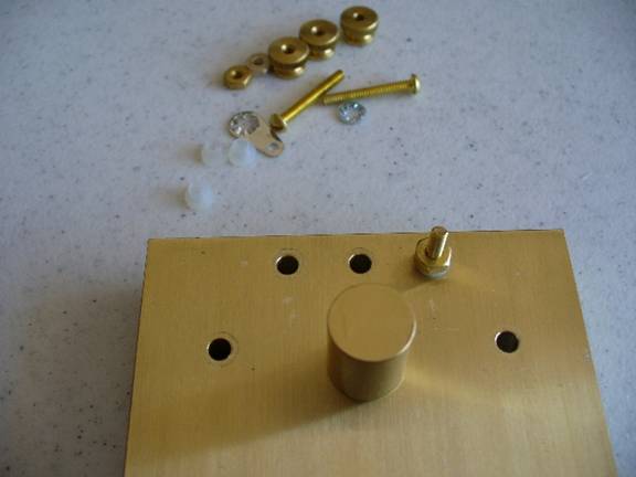
Figure 6
In a similar manner, install
the same hardware into the other outside knurled nut hole. Place a lock washer over a 7/8 inch brass
screw and insert the screw through the center knurled nut hole from the
bottom. Place a nylon shoulder washer
over the screw on the top of the base.
Screw a hex nut onto the 7/8 inch screw and tighten using a screw
driver.
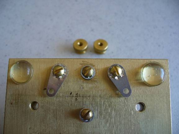
Figure 7
Screw the knurled nuts onto
the 7/8 inch screws. Using an ohm meter,
insure that the outside knurled nuts/screws are insulated from the base. Insure the center screw is shorted to the
base.
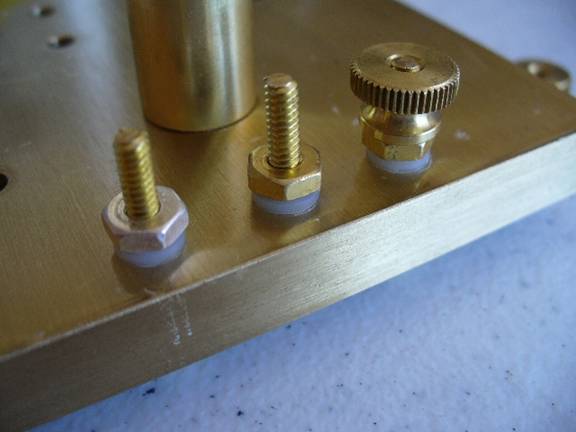
Figure 8
Refer to Figure 9. Preassemble the contact posts. You will need 2 machined brass contact posts,
2 Red head ¼ inch lock screws, and 2 Red head Silver Plated screws.
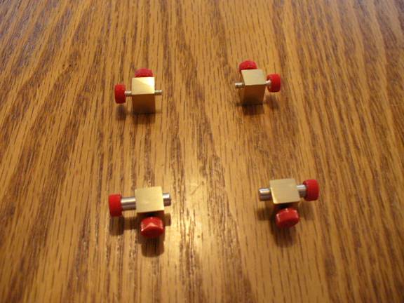
Figure 9
Mount the preassembled
contact posts to the base using two 5/8 inch brass screws, 2 ground lugs, and 4
shoulder washers. The contact post must
be insulated from the base.
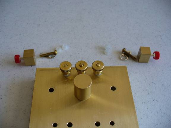
Figure 10
To mount a contact arm, place
one of the ground lugs and a shoulder washer over the brass screw. Make sure you orientate the shoulder washer
correctly. Push the screw through the
base and put and additional shoulder washer over the top of the screw. Using a small screw driver, tighten the screw
into the bottom of the contact post. Align
the contact post as is shown in Figure 13.
Align the ground lug as is shown in Figure 12. Figure 11 shows the shoulder washer under the
screw and lug. Using your ohm meter
verify that the contact post is not shorting out to the base. In a similar manner, mount the other contact
post.
Figure 11
Figure 12
Figure 13
Mount the hex spacers. Refer to Figure 14 and 15. Using 1 lock washer, 2 brass screws, and 1
ground lug, loosely mount the hex spacers.
Do not tighten the screws at this time.
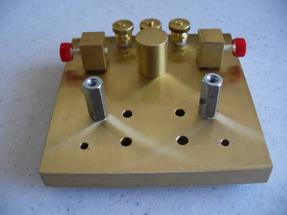
Figure 14
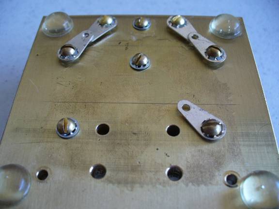
Figure 15
Refer to Figure 16 and place
2 ball bearings on the holes in the base as is shown. The arms will ride on these 2 bearings. Note:
it is very important that the holes that the bearings ride on have been
deburred. The edge of the hole should be
smooth and free of any sharp points.
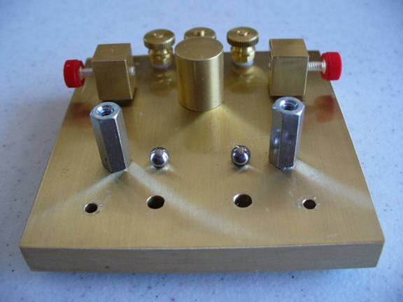
Figure 16
Assemble the arms as is shown
in Figure 17. You will need four 4-40 x
¼ inch Zinc Plated screws, 2 Silver Plated 4-40 x ¼ inch screws, and 2 finger
pieces. Insure that the holes in the
arms have been deburred since the ball bearing will ride on these holes. Please note:
If you did not solder the wires to the arms, then you must now clamp the
two wires under the ¼ inch zinc plated screws used to attract the magnets.
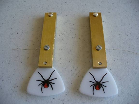
Figure 17
To mount the arms, refer to
Figures 18 through 22. You will need the
following parts. 2 red head 5/8 inch socket
screws, two 3/16 inch diameter x ¼ inch springs, the brass tension bar, and 2
ball bearings. Place the springs over
the Red head 5/8 inch socket screws as is shown in Figure 18.
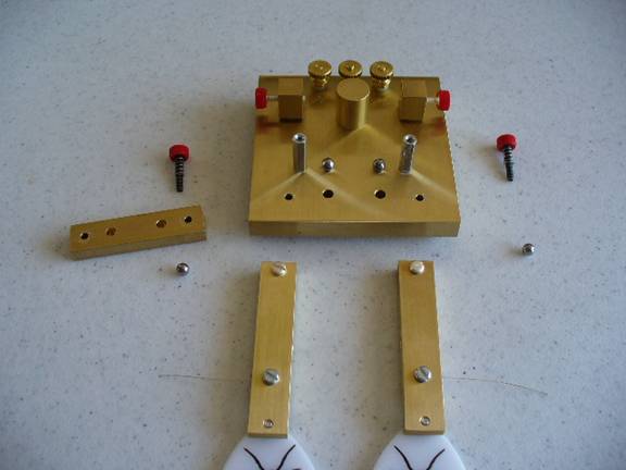
Figure 18
Place the arms on the base
lining up the holes in the arms with the bearings on the base. Make sure the
two wires are routed through the correct holes under the magnet attracting
screws. See Figure 19 and Figure 23
further down below.
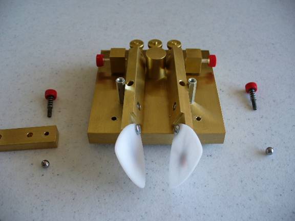
Figure 19
Holding the arms with one
hand, place the bearing on the top of the holes in the arms as is shown in
Figure 20.
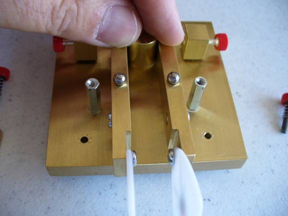
Figure 20
Place the tension bar over
the bearings and start one of the Red head socket screws (make sure the small
spring is still over the screw threads) into the hex spacer as shown in Figures
21 and 22. In a similar manner, screw
the other Red head socket screw into the other hex spacer.
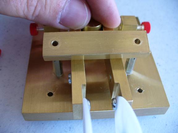
Figure 21
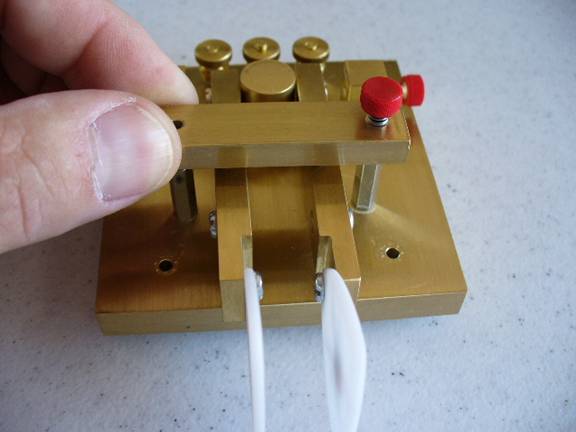
Figure 22
Tighten down the screws
holding the hex spacers as is shown in Figure 23.
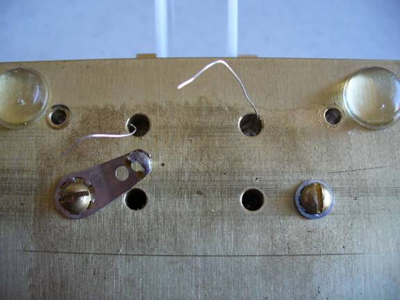
Figure 23
Refer to Figure 24. Mounting the spring requires the use of
needle nose pliers. Using the pliers, carefully
compress the spring in the center and insert it into the recessed holes in the
arm. Several people who built the AZ
ScQRPion Paddle had problems losing the spring.
Someone suggested putting a 12 inch length of thread through the center
of the spring so you can hold onto it in case the spring should go flying. If you do loose the spring, check with Chuck
Adams, K7QO, to find out how to locate lost springs! Chuck gets down on his hands and knees and
uses a flashlight shinning parallel to the floor. The spring will cast a large shadow.
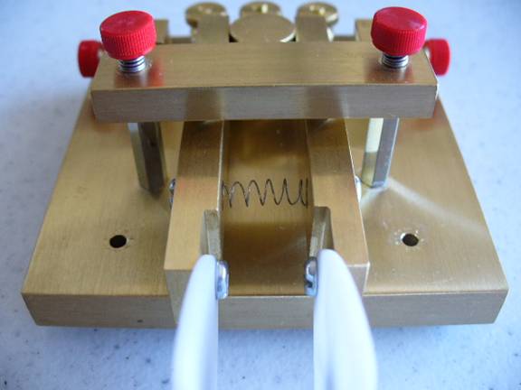
Figure 24
Preassemble the magnet post
as is shown in Figure 25. Lock the
magnet with the knurled screw. Using a 1/2
inch brass screw and #4 lock washer, mount the magnet posts as shown in Figures
25 and 26. Note that the washer goes on
the top of the base.
Figure 25
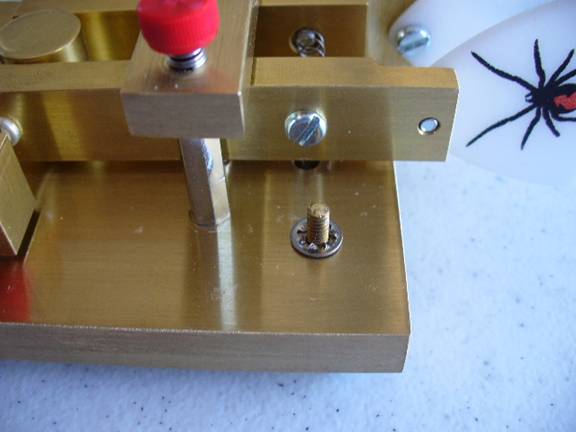
Figure 26
Refer to Figure 27. The next step of the assembly process is to
solder the wires to the ground lug under one of the screws used to hold the hex
spacer. Trim the length of the wire as
necessary. You will also need to solder
the ground lugs connected to the knurled nuts and the contact posts as is shown
in Figure 27.
The last step of the assembly
process is to mount the plastic feet.
Stick the feet down in the corners of the paddle. I put a lot of pressure on them for small
amount of time to help seat them. This
completes the assembly of the Black Widow paddle. The last section of this document gives you
some adjustment tips.
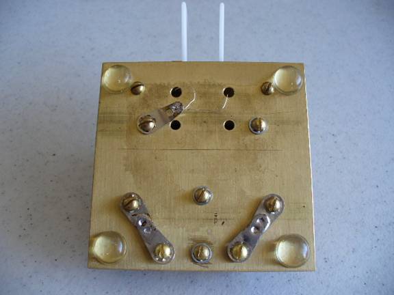
Figure 27
Figure 28
Adjustment
The Black Widow is easy to
adjust. First, with the contacts opened
up wide, move the paddle arms back and forth to see how easy they are to
move. Adjust the tension bar screws (The
black screws with the red heads) to apply tension to the bearings. Excessive tension will lock the bearings and
too little tension will allow the arms to move up and down an excessive
amount. By moving the arm back and
forth, you can feel the difference.
After adjusting the bearing tension, you can set the contact spacing. Most high speed operators like a very close
spacing. Loosen the lock screw on the
contact post. Thread the contact toward
the arm setting it to the desired distance.
Tighten the lock screw when the optimum spacing has been acquired. In a similar manner, set the spacing for the
opposite contact. The last adjustment
sets the arm return force. Some operators like a very light return force. If that is the case, you may not want to move
the magnets very close and only use the spring as the return force. If you want a stiffer feel, move the magnets
closer to the arms. The name of the game
here is experiment. Find what you like
and then lock everything down. It will
stay that way for years.
Optional fingers pieces are
available. See Figure 28 for a picture
of the “oblong” style of finger pieces.